Using thrust plates -VW 401-/-VW 402-, press tools -VW 408 A-/-VW 411-, tube -VW 416 B- and circlip pliers -VW 161 A-, this page covers dismantling the Volkswagen Golf Mk7 VL100 drive shaft joint.
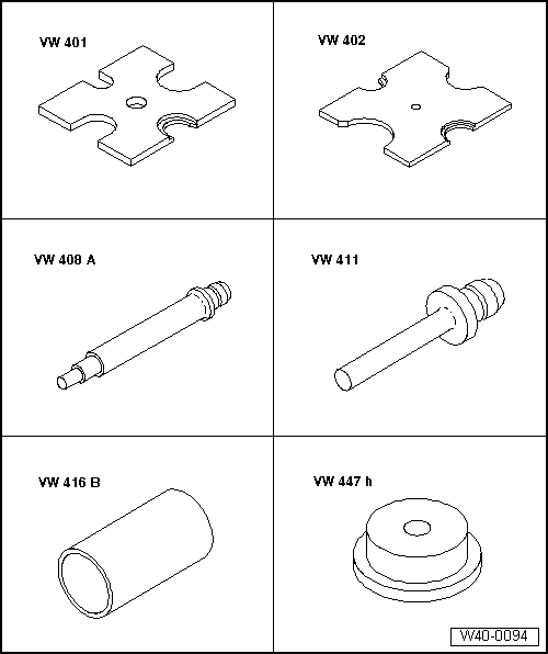
| Special tools and workshop equipment required |
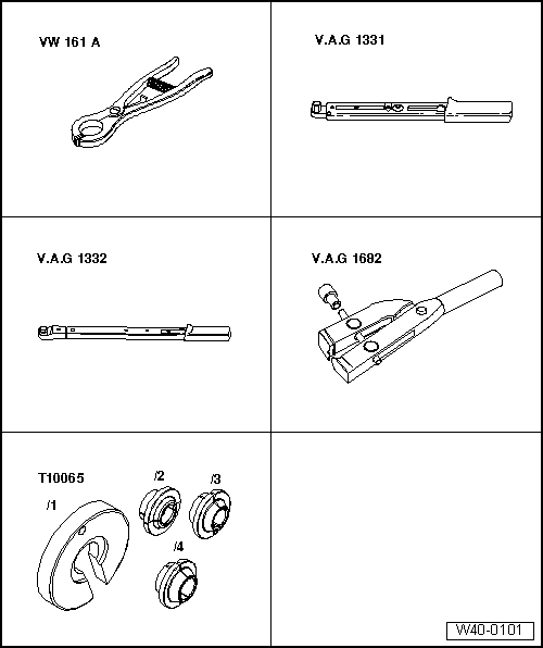
| Circlip pliers -VW 161 A- |
| Torque wrench -V.A.G 1331- |
| Torque wrench -V.A.G 1332- |
| Special pliers -V.A.G 1682- |
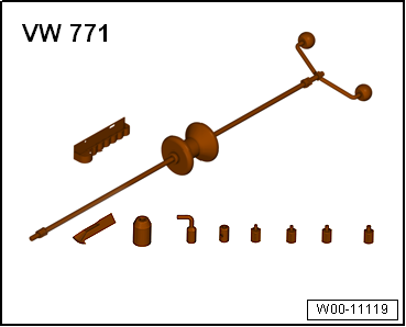
| Multi-purpose tool -VW 771- |
|
|
|
| Removing outer constant velocity
joint |
| – |
Clamp drive shaft in vice using protective jaw covers. |
| – |
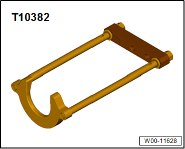
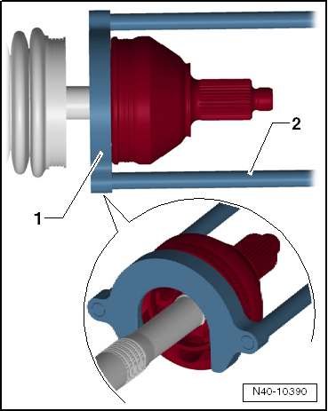
Set puller -T10382- up so that smooth side of puller plate
-T10382/1- points to spindles -T10382/2-. |
| – |
Assemble puller -T10382- complete with multi-purpose tool -VW
771-. |
|
|
|
| – |
Pull constant velocity joint from drive shaft with puller
-T10382- and multi-purpose tool -VW 771-. |
| 1 - |
Puller plate -T10382/1- |
| Driving on outer constant velocity joint |
|
|
|
| Installation position of dished spring and thrust washer on
outer joint |
| – |
Install new retaining ring. |
| – |
If necessary, push new joint boot onto drive shaft. |
| – |
Knock onto shaft with plastic hammer until circlip engages. |
|
|

|
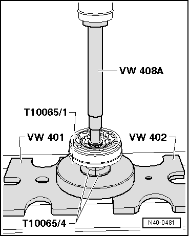
| Pressing off inner constant velocity joint |
|
|
|
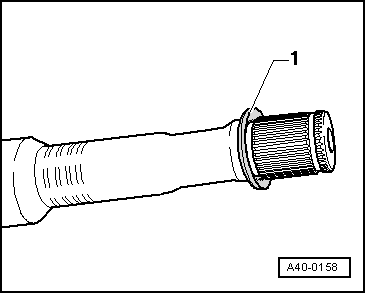
| Installation position of dished spring at inner joint |
|
|
|
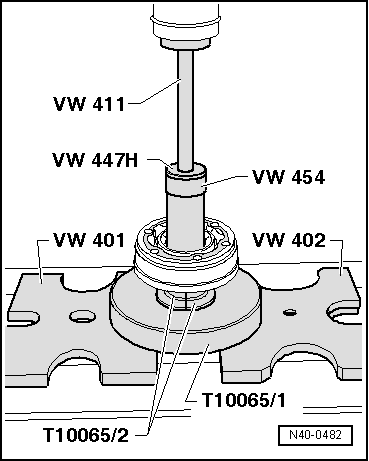
| Pressing on inner constant velocity joint |
 Note Note
| Chamfer on internal circumference of ball hub (splines) must
face contact shoulder on drive shaft. |
|
|
|
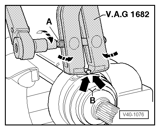
| Tighten clamp on outer joint |
| – |
Position clamp tensioner -V.A.G 1682- as shown in diagram.
Ensure jaws of tensioner lie in corners
-arrows B- of ear on O-type clip. |
| – |
Tighten clamp by turning spindle with a torque wrench (do
not cant pliers).
|
Note
| Due to the hard material of the protective boot (compared to
rubber) and the necessity of using a stainless steel clamp, it
is only possible to tension the clamp with clamp tensioner -V.A.G
1682-. |
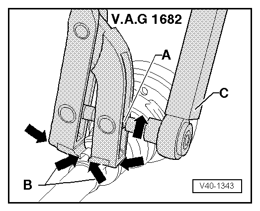
| Use torque wrench -C - with
setting range of 5 ... 50 Nm (e.g. torque -V.A.G 1331-). |
| Make sure thread of spindle -A-
on pliers moves freely. Lubricate with MoS2 grease if necessary. |
| If the thread is tight (e.g. due to dirt), the required
clamping force for the clamp will not be attained although the
specified tightening torque is applied. |
|
|
|
| Tightening clamp on small diameter |
|
|
|
Questions & answers
Dismantling and assembling drive shaft, constant velocity joint VL100 — Volkswagen Golf Mk7
How do I dismantle a Golf Mk7 VL100 CV joint?
Cut off the boot clamps, slide the boot back, remove the circlip, tap the joint off the shaft, clean and repack with fresh grease, fit new boot and clamps.
Front-wheel drive:
Component
Specified
torque
Bolts -1-
25 Nm
&n ...
Special tools and workshop equipment required
Thrust plate -VW 401-
Thrust plate -VW 402-
Press tool -VW 408 A-
Support ...
Other materials:
- Assembly overview - drive shaft, triple roller joint AAR3300i
- Assembly overview - drive shaft, constant velocity joint VL107
- Removing and installing drive shaft, left drive shaft, constant velocity joints VL100 and VL107, except for e-Golf
- Removing and installing drive shaft, left drive shaft, constant velocity joints VL100 and VL107, e-Golf
- Removing and installing drive shaft, right drive shaft, constant velocity joints VL100 and VL107, except for e-Golf

 Removing and installing drive shaft heat shield
 Dismantling and assembling drive shaft, constant velocity joint VL107