 Note Note
| The arrows point in the direction of coolant flow. |
| The arrows on the coolant pipes and on the ends of the hoses
must be aligned with each other. |
|
|
|
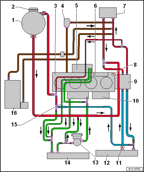
| 1 - |
Coolant expansion tank |
| For coolant expansion tank |
| Check pressure relief valve
→ Anchor |
| 3 - |
Cylinder head/cylinder block |
| Change coolant after renewing. |
| 4 - |
Engine preheating element -Z97- |
| Only for engine codes CPVA, CPVB |
| 6 - |
Integrated exhaust manifold |
| 7 - |
Heat exchanger for heater unit |
| Change coolant after renewing. |
| 8 - |
Coolant temperature sender -G62- |
| 11 - |
Radiator outlet coolant temperature sender -G83- |
| Change coolant after renewing. |
| 13 - |
Charge air cooling pump -V188- |
| 14 - |
Radiator for charge air cooling circuit |
| Change coolant after renewing. |
| 15 - |
Charge air cooler in intake manifold |
| Change coolant after renewing. |
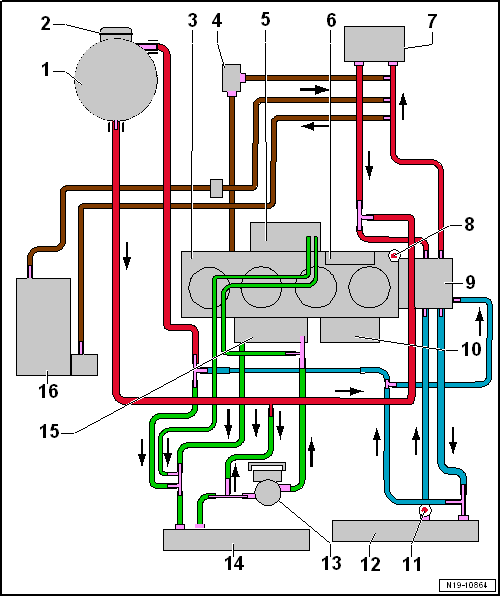
| 1 - |
Coolant expansion tank |
| For coolant expansion tank |
| Check pressure relief valve
→ Anchor |
| 3 - |
Cylinder head/cylinder block |
| Change coolant after renewing. |
| 4 - |
Engine preheating element -Z97- |
| Only for engine codes CPVA, CPVB |
| 6 - |
Integrated exhaust manifold |
| 7 - |
Heat exchanger for heater unit |
| Change coolant after renewing. |
| 8 - |
Coolant temperature sender -G62- |
| 11 - |
Radiator outlet coolant temperature sender -G83- |
| Change coolant after renewing. |
| 13 - |
Charge air cooling pump -V188- |
| 14 - |
Radiator for charge air cooling circuit |
| Change coolant after renewing. |
| 15 - |
Charge air cooler in intake manifold |
| Change coolant after renewing. |
Questions & answers
Coolant hose schematic diagram — Volkswagen Golf Mk7
What does the Golf Mk7 1.4 TSI coolant hose diagram show?
The full coolant routing: engine → heater matrix → thermostat → radiator → pump, plus auxiliary circuits for turbo, oil cooler and cabin heater.
Special tools and workshop equipment required
Refractometer -T10007 A-
Drip tray for workshop hoist -VAS 6208-
Hose clip pliers -VAS 634 ...


